
Top roller embossing knife type top roller embossing machine
The punch-knife top roller gin is composed of main parts such as a frame, a front horizontal plate, a top roller, a fixed knife, a movable knife, a crankshaft, a push plate and a cotton seed grid, as shown in Figure 8-28.
![]()
1. Rack
The rack is composed of wall panels and braces. The wall panel is made of cast iron and divided into left and right pieces, which can be fixed on the anchor bolts of the horizontal foundation respectively. The two wall panels are connected laterally by 4 or 5 support rods to form a stable whole. The holes and slots on the frame are used to accommodate various components.
2. Front transverse plate
The front transverse plate is made of pig iron, and its two ends are fixed to the upper parts of the left and right wall panels with bolts as the cross beams of the rack. A straight step groove with the same thickness as the fixed knife is milled out on the lower end of the plate to install the fixed knife. A number of holes are arranged horizontally on the upper part of the front transverse plate at regular intervals for use when installing the arcuate pressure plate. The fixed knife is clamped between the front horizontal plate and the bow pressure plate. By adjusting the bolts of the bow pressure plate, the pressure of the fixed knife on the top roller can be adjusted. The installation diagram of the fixed knife is shown in Figure 8-29.
3. Fixed knife
The fixed knife is made of low carbon steel plate, with a blade width of 82~95mm and a thickness of 2~3mm. One side of the fixed knife is cut into a bevel, the bevel width is 32~38mm, and the blade thickness is 0.4~0.8mm. The entire length of the lower end of the fixed knife is close to the surface of the top roller. The width and thickness of the entire knife must be uniform, otherwise the fixed knife will easily bend longitudinally during work, causing uneven pressure on the top roller, causing uneven surface of the top roller and damaging the blade. The blade of the fixed knife should also maintain a certain thickness, but it should not be too thick. If the blade is too thick, cotton or large impurities will be retained on the blade. When the knife moves upward, the sticky cotton or large impurities will be squeezed and broken. Increase impurities in lint. If the blade is too thin, the blade will easily curl.
4. Top roller
Top roller is composed of three materials: steel, wood and leather strips. The axis of the top roller is made of square steel to reliably transmit torque. The exposed parts of the top roller at both ends are arranged in a cylindrical shape to install bearings and pulleys. The middle layer of the top roller is made of hard wood. Two semicircular wooden rollers are combined to enclose the axis. They are fixed to each other with through-bolts, and the periphery is fixed with steel hoops. The outer layer of the top roller is spirally wrapped with leather strips of uniform thickness on the surface of the wooden roller, and the leather strips are bonded with glue.
The bearings at both ends of the top roller shaft can move forward and backward on the frame. After the top roller is worn, the bearings at both ends can be moved to maintain close contact with the fixed knife. The friction and traction force of the top roller on the cotton fiber has a great relationship with the pressure of the fixed knife. In addition, the leather strap material is also an important factor that cannot be ignored. The top rollers that are used for a long time will be worn, so the leather strips should be made of uniform, fine, and compact materials. Firstly, it can increase the service life; secondly, it can cause wear and tear evenly to maintain the shape of the top roller; thirdly, it can maintain the shape of the top roller after wear. Roll original quality. The leather strip should have a certain elasticity and a certain roughness. The leather roller should not be too hard or prone to heat. It should be degreased in advance and the fat content should not exceed 2.5%.
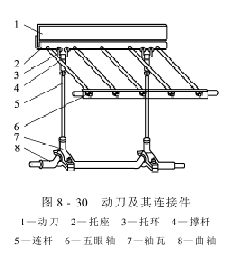
5. The movable knife and its connecting parts
The movable knife is also made of low carbon steel plate, with a width of 90~95mm and a thickness of 3~4mm. The movable knife and its connecting parts are shown in Figure 8-30. The back of the movable knife is riveted on the bracket. Five round holes are evenly opened on the side of the bracket. One end of the five support rods is inserted into the round hole of the bracket. And fix it with bolts. The other end is threaded, penetrates into the five-eye shaft of rectangular cross section, and tightens with nuts. Both ends of the five-eye shaft are fixed on the wall panels on both sides. The lower end of the bracket is equipped with a supporting ring loop, through which the connecting rod is connected.
Under the knife It is used to exert impact force on the cotton to separate the cotton from the fibers and knock down some larger impurities to a certain extent. During the work process, the movable knife is subject to alternating stress and is prone to fatigue damage. The matching distance between the movable knife and the fixed knife should be consistent. The knife must be straight and smooth.
The movable knife edge should not be too thin to avoid deformation when the movable knife impacts the cotton, causing the distance to change; the moving knife edge should not be too thick to avoid increasing the impact load on the crankshaft and colliding with the grid head of the cotton grid.
The connecting rod is made of round steel. The upper end is connected with the connecting rod loop and the supporting ring loop. The lower end is connected with the upper bearing bush. The upper and lower ends are machined into left and right threads respectively and tightened with nuts. The middle part of the connecting rod is a square diameter. By turning the connecting rod’s square diameter, the length of the connecting rod can be adjusted through the left and right threads at both ends. The connecting rod is the component that connects the movable knife and the crankshaft. The up and down reciprocation of the movable knife is caused by the rotation of the crankshaft. The two connecting rods on the left and right should stand parallel to each other and be adjusted at the same height to avoid assembly stress, bending of the connecting rods, etc.
The crankshaft is also made of round steel. There are two symmetrical cranks on the crankshaft, which are installed in the bearings at the lower ends of the two connecting rods.
The crank radius is 15~32mm. Rolling bearings are installed at both ends of the crankshaft and installed in the bearing seat at the bottom of the wall panel.
The speed of the crankshaft is related to the impact frequency of the moving knife on the cotton seeds, which directly affects the output of the top roller gin. However, increasing the crankshaft speed will intensify the vibration of the machine, thereby affecting the distance and even causing the crankshaft to break.
6. Cotton grid
Cotton grid is composed of beams and bars.As shown in Figure 8-31. The cross beams are two 25mm wide flat steels with holes drilled at equal distances. The diameter of the holes is determined according to the thickness of the steel wire. The steel wires are inserted into the holes of the cross beams and riveted tightly to prevent the bars from loosening and are evenly arranged on the two cross beams. The clear distance between the grids should be larger than the cotton waist diameter, generally around 7.5mm. There are two flat steels on the grid surface, which are push board runways (or skateboards). Thin steel plate hanging feet are installed at both ends of the cotton grid. There are rectangular holes on the hanging feet to adjust the position of the cotton grid and be fixed on the rack wall plate with screws.
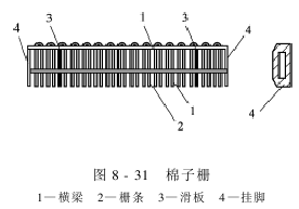
Cotton seeds The grid is mainly used to receive the fed cotton and the unrolled clean cotton impacted by the movable knife, and guide the push plate to continuously push the cotton to the surface of the top roller, and make the cotton and impurities pass from the grid head and the grid. Rows between strips.
7. Push flower board
Push flower board is made of wood or aluminum plate. The front end of the push flower board is free, and the rear end is connected to two connecting rods. The two connecting rods are connected to the push plate crankshaft through the connecting rod ring. The crank radius of the crankshaft is generally 25mm, so the stroke of the push plate is about 50mm.
When the crankshaft of the flower push plate rotates, the crank connecting rod mechanism drives the flower push plate to reciprocate on the cotton grid. The main function of the push plate is to push the cotton fed into the cotton grid to the surface of the top roller, creating conditions for full contact between the cotton and the surface of the top roller. At the same time, rub and push the waste and impurities staying on the cotton grid to make them fall from the grid holes. The flower push plate itself should be straight and smooth, and its front end should be in close contact with the cotton seed grid surface to push away the cotton seeds and cotton seeds on the cotton seed grid. The number of reciprocating pushes of the flower board should be coordinated with the number of impacts of the knife and the speed of the top roller.
8. Cotton pulling device
The rolled lint should be separated from the top roller in time, otherwise the cotton fiber will be brought back to the fixed knife edge, and the fixed knife will bend, the moving knife will hit the fixed knife, and the fixed knife will cut the top roller. accident.
There are two types of cotton-picking devices that are more common now. One is to use a rectangular sloped drip plate. The upper edge of the plate is close to the top roller, and the lower edge is connected to the cotton box. The lint on the top roller is blocked by the edge of the drip plate and flows into the cotton box along the drip plate. The other uses a lint-picking roller. The lint-picking roller and the top roller are placed in parallel. The roller surface is engraved with eight circular grooves in the shape of a gear. Round blade baffles are installed at both ends to prevent lint from moving out of the two ends of the lint-picking roller. Wrapped around a shaft or bearing. The surface of the lint-picking roller should be completely smooth, with the same direction of rotation as the top roller, but the rotation speed should be higher than the top roller, so that its surface linear speed is higher than or equal to the top roller’s linear speed, which is beneficial to pulling off the lint fibers on the top roller. There should be a gap of 2 to 3 mm between the top of the tooth groove on the surface of the cotton roller and the surface of the top roller so that the two rollers do not collide and small impurities can fall from them.
The cotton is fed to the cotton grid at the front of the push plate by a flower feeding machine or manually. Due to the inclination of the cotton grid and the back and forth movement of the push plate, the cotton is pushed to the top roller. When the cotton is pressed against the rough-surfaced roller with a certain amount of pressure, sufficient friction is generated to cause the cotton fibers to follow the rotating roller and enter the edge of the fixed knife. Because the fixed knife is pressed against the top roller with a certain pressure, that is, the surface of the fixed knife and the top roller is in close contact, so the cotton cannot pass through and is blocked at the fixed knife edge. However, the friction force of the cotton fiber on the surface of the top roller is much greater than that of the fixed knife. Because of the friction of the knife, the soft and thin cotton fibers can continue to rotate with the top roller. The traction force of the surface of the top roller on the fiber is not enough to overcome the force of the fiber on the cotton. At this time, relying on the rotation of the crank to reciprocate up and down, the movable knife impacts the cotton seeds staying at the fixed knife edge, causing the cotton seeds and fibers to be acted upon by forces in different directions, promoting the separation of cotton seeds and cotton fibers. The separated cotton fibers still rotate with the top roller and are pulled off when they turn to the cotton-picking device position. After rolling, some large impurities such as cotton seeds and small stiff flaps fall from the grid head of the cotton grid and the gap between the grid bars, while some small impurities often enter the fixed knife edge with the top roller and are mixed into the lint.
AAAE4T45UY75T