
Lint cleaning sawtooth lint cleaning machine
Sawtooth lint cleaning machine, that is, sawtooth roller lint cleaning machine, also known as lint cleaning machine. According to the different brushing methods, it can be divided into two types: air flow type and brush type. Domestic sawtooth lint cleaning machines are all brush type, and the structural composition is similar.
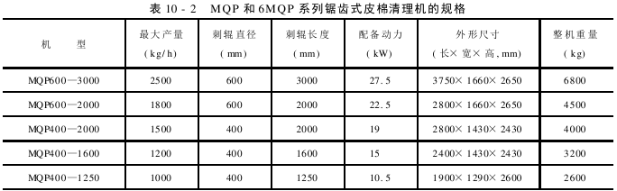
At present, the cleaning rates of common domestic lint cleaning machines on the market are 30% to 40%. The specifications of MQP series and 6MQP series lint cleaning machines are shown in Table 10-2.
(1) Working principle of sawtooth lint cleaning machine
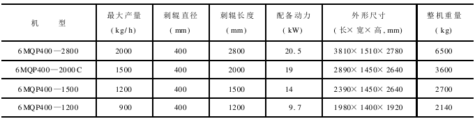
As shown in Figure 10-2, lint is removed from the lint of the gin. It is sent to the lint collection cage through the four-way valve, reducing pipe and right-angle pipe under the blowing of the air flow from the brushing fan and the suction of the lint cleaning machine. The dust-containing airflow enters the distribution air duct from the air ducts at both ends of the dust cage and is discharged into the dust chamber.
Lint patch Attached to the dust cage, as the dust cage rotates clockwise, it is pulled down by the cotton roller. The lint-moving roller and the lint-pressing roller rotate in opposite directions to send the lint to the drafting roller for drafting. The drafting roller and the drafting roller rotate in opposite directions to form a continuous and uniform batt, which is sent to the cotton feeding roller and the cotton feeding plate. The cotton batting is evenly pulled and combed by the rack roller under the grip of the cotton feeding roller and the cotton feeding plate. The pulled fibers rotate at high speed with the rack roller. Due to the heavy weight of infertile particles, natural impurities and large defects, they are discharged under the action of centrifugal force and blocked by 5 dust rods, fall into the trash discharge box, and enter the recycling equipment through the suction duct for cleaning and recycling. When the cotton fibers hooked and carded by the rack roller meet the brush roller, they are blown down by the high-speed rotating bristles of the brush roller, and are sent away by the wind force of the brush, and are pressed into cotton sheets through the lint cotton path to the cotton collecting part. Enter the baler to make cotton bales.
(2) The structure of the sawtooth lint cleaning machine
The sawtooth lint cleaning machine consists of four parts: lint collection, lint feeding, lint cleaning and lint brushing.
1. Cotton collection part
The cotton collection part is mainly composed of four-way valve, right-angle pipe, cotton collection dust cage, air duct, cotton pressing roller and cotton dialing roller.
The function of the lint collection part is to separate the loose lint blown out by the brush roller of the gin brushing part and the air flow, and at the same time press the loose and uniform lint into cotton batting, send it to the lint feeding part, and use the dust net to remove some fine lint Impurities are discharged with the air flow and enter the dust chamber through the exhaust duct.
The four-way valve is equipped with four channels. By moving the blade in the middle, the leisure route of the lint can be changed, and the lint channel can be cleaned and adjusted. The four-way valve and the entrance of the lint collection cage are connected by a right-angle pipe. In order to ensure the transportation of lint and the dust cage net, the air flow speed in this pipe section is required to be greater than or equal to 9m/s. The lint collecting cage is located on the upper part of the lint cleaning machine. Its diameter, working length and rotation speed must be determined to meet the requirements of large processing capacity. There are two main structures of cotton dust cages, one is a woven mesh dust cage, and the other is a steel plate dust cage. Their basic skeletons are composed of shafts, spoke wheels and flat steel. The cotton pressing roller and cotton dialing roller are located at the bottom of the dust cage. They are generally made of No. 45 steel pipes with grooves arranged in a certain shape on the surface. On the one hand, the pressing roller plays the role of compacting the cotton batting, and on the other hand, it cooperates with the cotton picking roller to feed the cotton batting to the cotton feeding part. The cotton removing roller mainly plays the role of removing the cotton on the surface of the dust cage. The pressing roller and the cotton picking roller have the same diameter and the same speed, but have opposite directions. The gap between the cotton pressing roller and the dust cage is 3~5mm, the gap between the cotton pressing roller and the dust cage is 0.3~0.6mm, and the gap between the cotton pressing roller and the cotton picking roller is 2~2.5mm. The smaller the resistance of the air duct, the better, but it is necessary to ensure that the air outlet from the dust cage is even, otherwise it will affect the even distribution of lint on the dust cage. In order to ensure uniform airflow from the dust cage, the dust cage adopts double-sided exhaust.
2. Cotton feeding part
The cotton feeding part consists of cotton dialing roller, drafting roller, drafting roller, cotton feeding roller and cotton feeding plate.
The function of the cotton feeding part is to peel off the cotton batting on the dust web and send it to the drafting roller for drafting to make the cotton batting thinner. Through the action of the cotton feeding roller and the cotton feeding plate, a uniform and continuous thin cotton batt is provided for rack roller cleaning.
The drafting roller and the drafting roller are located below the pressing roller and the cotton-picking roller. In order to make the batt thinner, its surface linear speed should be higher than the surface linear speed of the pressing roller and the cotton-picking roller. The gap between the roller and the drafting roller is 6mm, which is formed by mechanical finishing.
The cotton feeding roller and the cotton feeding plate are the key components of the cotton feeding part. Through their function, the cotton batt will become thinner, and their working conditions will directly affect the impurity cleaning efficiency of the lint cleaning machine. The bearing seat installed with the cotton feed roller relies on the action of the spring to move or swing, so that the cotton feed roller presses against the cotton feed plate with a certain pressure. When the thickness of the cotton batt changes, the lint fiber can be clamped without clogging. . The curvature radius of the working arc surface of the cotton feeding plate gradually decreases. In order to enhance the ability of the cotton feeding plate to resist deformation, a supporting point can be set in the middle. The linear speed on the surface of the cotton feeding roller should be higher than the linear speed on the surface of the drafting roller., when the lint enters between the cotton feed roller and the cotton feed plate, the cotton batt becomes particularly thin, which is conducive to the rack roller fully combing and cleaning. The gap 5mm upward from the nose tip of the working arc surface between the cotton feeding roller and the cotton feeding plate is only 0.2~0.4mm.
3. Cleaning part
The cleaning part mainly consists of a rack roller, a dust removal knife (dust rod), a rack roller guard, and a waste removal box.
The function of the cleaning part is to fully decompose and comb the lint fibers through the cooperation of rack rollers, trash removal knives and other components, remove impurities in the cotton fibers, and improve the appearance of the lint.
The rack drum is composed of a cylinder, a rack, and a fan blade. The cylinder is made of cast iron and has spiral grooves on its surface. The rack is embedded in the groove on the surface of the cylinder using a special cog machine. There are two types of racks: general racks and self-locking racks. Using a self-locking rack, no grooves are required on the surface of the cylinder. Rack specifications vary depending on the machine model. The rack working angle, tooth pitch, tooth tip thickness, and tooth tip depth are the main factors that affect the combing effect of the rack drum. The fan blades are made of steel plates and installed on both end faces of the rack drum. Their function is to prevent fibers from wrapping around the shaft of the rack drum. There are very high requirements for the production and installation of rack rollers. The surface linear speed of the rack drum has a great influence on the impurity cleaning efficiency, lint yarn performance and length damage, etc. There are generally 5 to 6 debris removal knives, evenly distributed around the rack drum. The function of the impurity removal knife is to impact the impurities exposed on the surface of the rack drum and dispersed along with the rack drum, so that the impurities and fibers are separated, and it also supports the fibers on the surface of the rack drum. The installation position and installation angle of the dust collector have a great impact on the cleaning efficiency and waste loss. The rack roller guard is located at the lower part of the rack roller. It is arc-shaped and can be adjusted up and down. It not only blocks impurities but also supports fibers. The gap between the rack roller guard and the rack roller is 2 to 6 mm. The trash discharge box is located under the rack drum and is connected to the trash suction pipe. The diameter of the getter tube is 150~200mm. The impurities falling in the waste discharge box are sent to the cleaning and recycling equipment through the getter tube.
4. Cotton brushing part
The cotton brushing part is mainly composed of brush roller, brush cover, air supply adjusting plate, rear windshield, cotton smoothing board, etc.
The function of the brushing part is to brush the fibers off the rack roller through the brush roller and transport them into the lint channel.
The brush roller is composed of several aluminum flanges fixed on a shaft, wrapped with galvanized steel plates and equipped with brush strips. In order to ensure clean cotton brushing, the surface linear speed of the brush roller should be 1.5 to 2 times the surface linear speed of the rack roller, and the gap between the brush bristles and the rack should be 0 to 1mm. The rear end of the brush cover is equipped with an air supply adjusting plate so that the brush can receive an appropriate amount of air.
The rear windshield is located at the rear upper part of the brush drum and is connected to the lint channel. Its function is to prevent return air and cotton. Generally this gap is 2~3mm. The lint smoothing plate is located at the front end of the upper cover of the brush roller. Its function is to allow the lint brushed by the brush to smoothly enter the lint channel.
The lint rolled off by the sawtooth gin passes through the four-way valve and other components under the action of air flow, and comes to the surface of the cotton dust cage. Dust-laden air enters the inside of the dust cage and is discharged from the air duct. It enters the dust removal device through the return air duct and the fan. The lint is attached to the surface of the dust cage and is relaxed as the dust cage rotates. It is first compacted by the lint pressing roller, and then removed from the surface of the dust cage by the lint picking roller. Relying on the opposite rotation of the lint pressing roller and the lint picking roller, Feed the batting to the cotton feeding part. Due to the high linear speed of the drafting roller and the drafting finish roller, the batt is drawn and thinned, and is fed to the cotton feeder roller and cotton feeder plate. Under the joint action of the cotton feeding roller and the cotton feeding plate, the cotton batting becomes thinner and almost becomes a cotton film. The cotton batting is fed to the high-speed rotating rack drum under the clamping action of the cotton feeding roller and the cotton feeding plate. The rack roller fully hooks and combs the cotton batt, and the hooked fibers rotate at high speed with the rack roller. Due to the heavy weight of impurities such as infertile particles and broken particles, they are either directly thrown away under the action of inertial centrifugal force, or moved to the surface of the rack drum, where they are cut and impacted by a dust collector. The fiber is hooked by the rack roller and reaches the range of the brush bar. After being brushed by the brush, it is sent to the cotton collecting machine for processing.
(3) Electrical control system of sawtooth lint cleaning machine
The electrical control system of sawtooth lint cleaning machine varies greatly depending on the model. The following only takes the MQP400-2000 model as an example to introduce the lint. The electrical control system of the cleaning machine.
The lint cleaning machine has 2 electrical equipment: rack drum motor (15kW) – drives the rack drum and brush drum; lint feeding motor (5.5kW) – drives the drafting roller, drafting Finishing roller, cotton feeding roller, cotton pressing roller, cotton dialing roller and cotton dust collecting cage.
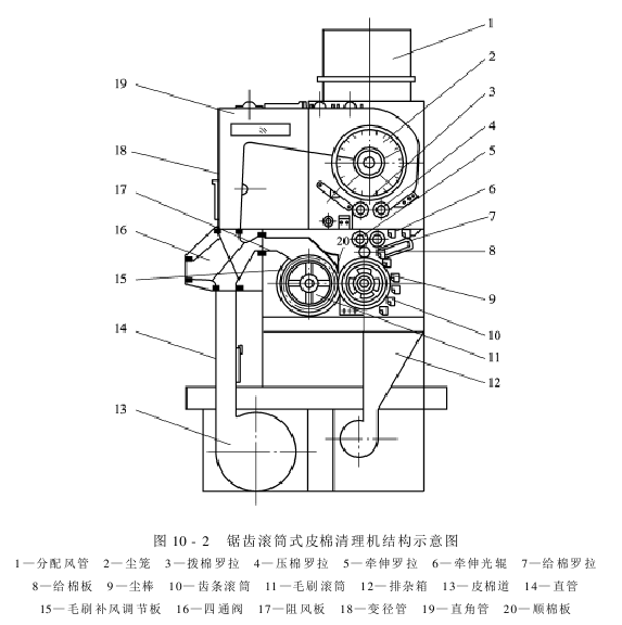
The principle of controlling the circuit is shown in Figure 10-3.
Key Switch S is in the working position, press the start button SB2, the intermediate relay KA is energized, its normally open contact is closed, and the control circuit power indicator light EL1 lights up. Press the start button SB1 of the rack drum motor, the AC contactors KM1 and KM2 are energized, and the motor is in “Y” connection Startup status. After a period of time, KM1 loses power, AC contactor KM3 gains power, the motor is in the “Δ” connected working state, and the rack drum motor working indicator light EL2 On. Press the start button SB6 of the cotton feeding motor, the AC contactor KM4 is energized, and the working indicator light EL3 of the cotton feeding motor lights up. During the production process, if you encounter an emergency and need to stop immediately, press the SB1 button to cause KA to lose power and cut off the main power supply.
The rack drum motor of the lint cleaning machine and the lint feeding motor are interlocked, and the lint feeding motor and the lint cleaning air net fan motor are interlocked. That is, if the rack drum motor does not start, the lint feeding motor cannot start, and the lint feeding motor cannot start. When starting, the lint cleaning air net fan motor cannot start.
AAASDFDNHGCXEThe current contactor KM3 is energized, the motor is in the “Δ” connected working state, and the rack drum motor working indicator light EL2 is on. Press the start button SB6 of the cotton feeding motor, the AC contactor KM4 is energized, and the working indicator light EL3 of the cotton feeding motor lights up. During the production process, if you encounter an emergency and need to stop immediately, press the SB1 button to cause KA to lose power and cut off the main power supply.
The rack drum motor of the lint cleaning machine and the lint feeding motor are interlocked, and the lint feeding motor and the lint cleaning air net fan motor are interlocked. That is, if the rack drum motor does not start, the lint feeding motor cannot start, and the lint feeding motor cannot start. When starting, the lint cleaning air net fan motor cannot start.
AAASDFDNHGCXE