
MDY-type hydraulic cotton baler common troubleshooting
1. Key points for troubleshooting
(1) Be familiar with the position and function of each switch of the baler.
(2) Be familiar with the working steps of each working mechanism of the baler.
(3) Understand the energization rhythm table of the electromagnet in each working step of the baler.
(4) Understand the operating principle of opening and closing the cartridge valve spool.
(5) Grasp the hydraulic principle of the MDY-400 baler, and understand which valve cores must be closed and which valve cores must be opened in a specific operation. If the valve core that should be closed cannot be completely closed and the valve core that should be opened cannot be opened, it will inevitably cause the oil flow to go in the wrong direction and cause a hydraulic failure.
(6) When a fault occurs, you cannot simply search for the cartridge valve part. Failures may also involve mechanical jamming, electrical failure, and failure of other hydraulic components. Therefore, when a fault occurs, it is necessary to conduct an all-round and careful inspection to distinguish the type of fault (mechanical, electrical, and then hydraulic) in order to quickly resolve the fault. In the process of troubleshooting hydraulic faults, be sure not to install the wrong items or backwards. Otherwise, not only the fault cannot be solved, but it will also become difficult to infer the fault.
2. Troubleshooting process and method
The troubleshooting process generally follows the order of mechanical first, then electrical, then hydraulic. Mechanically check for jamming, deformation, cracking, and wear. In terms of electrical aspects, you can understand the working conditions of a certain working mechanism of the MDY-400 baler by grasping the input and output status of the PLC module indicator light, compare the required working conditions, search and analyze the problems that arise. The usual process is to check whether each motor is running normally, whether the motor controller and protector are normal, whether each switch is working normally, whether the wiring is good, and whether there are any errors. Also check whether the pilot valves and pressure relays are working normally, whether the wiring is in good condition, whether there are any errors, and whether the pilot valves are powered according to the rhythm.
In terms of hydraulic pressure, if any hydraulic working mechanism behaves abnormally, you must first check whether the oil supply pressure is normal. Secondly, check the pilot valve and control oil line. Most of the failures of cartridge valves are related to the pilot valve and control oil circuit. Therefore, it is particularly important to check the pilot valve and control oil circuit. Finally, check the valve core and valve sleeve to see if there is any jamming, wear or damage.
For hydraulic faults, you should be familiar with the hydraulic schematic diagram and handle it according to the rhythm table of each working step below the hydraulic schematic diagram. When a hydraulic failure occurs, you also need to pay attention to whether the oil pump leisure pair is worn or failed (repair or replace it), whether the oil level in the oil tank is too low, whether the oil pump suction capacity is insufficient (add clean oil to the required amount), and whether the oil cylinder is leaking (replace the oil seal). )wait.
3. Solve the problem through the expert diagnosis system
When the baler is running automatically, if an error or malfunction occurs, the box of the working step usually flashes in red, and there is a box in the middle of the left side of the flow chart with text on it. :Alarm screen, click to enter. The interface title is: Alarm Record. Click on the alarm record bar that appears, and a solution interface will appear. The operator should be familiar with and apply this function for daily maintenance and troubleshooting of the baler. After the fault is resolved, return through the return arrow in the upper left corner to exit the alarm processing interface.
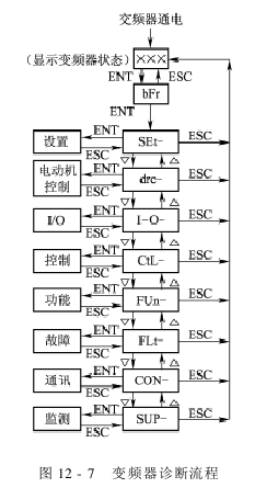
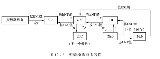
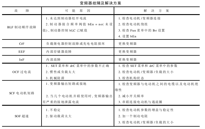
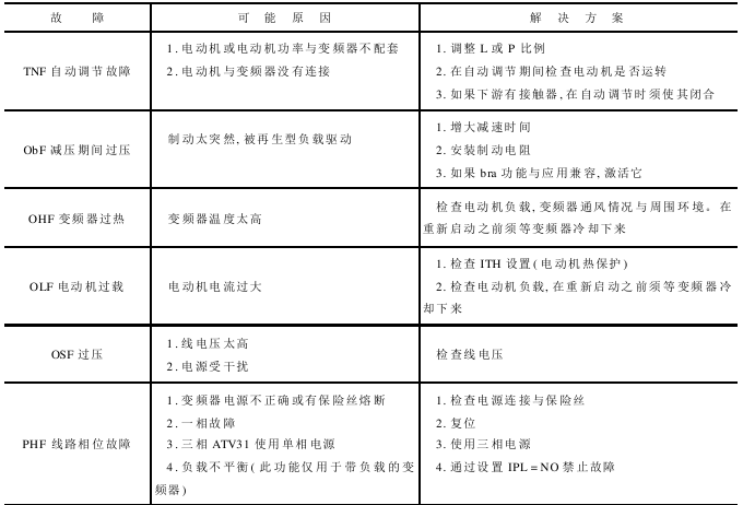
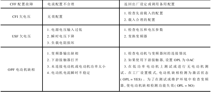
The frequency converter diagnosis flow chart is shown in Figure 12-7, the frequency converter diagnosis system diagram is shown in Figure 12-8, and the frequency converter faults and solutions are shown in the table below.
AAAGFREGRTTHR